Every rhythm. Every beat. Music isn’t heard, it’s felt.
Whether listening to somber melodies or the summer’s hottest hit, music is an emotional experience for many. Through light and motion, DotWave enhances those feelings by turning every song into an audiovisual experience.

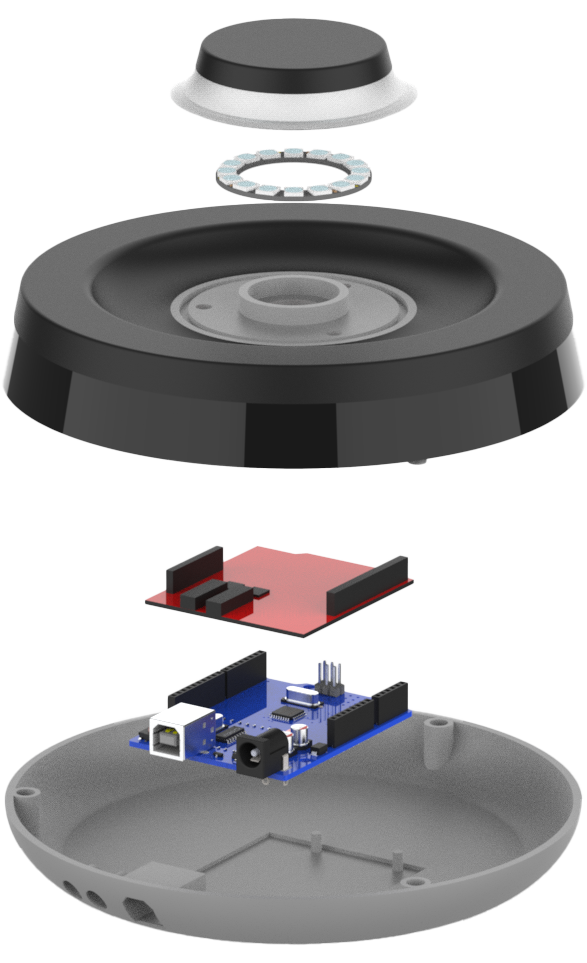
Components
Frosted diffuser
Top casing
RGB LED ring
SparkFun Spectrum shield
Arduino Uno
Bottom casing
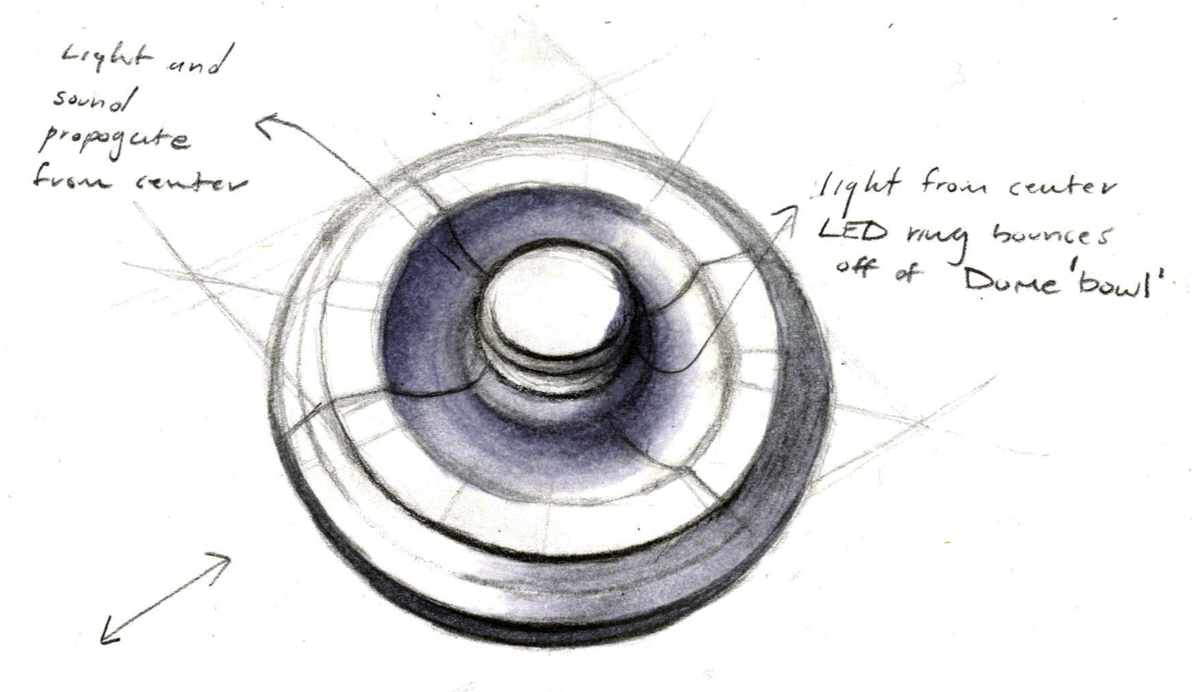
For this project, I looked to the natural occurring phenomenon of wave functions for inspiration, such as a water droplet falling on a calm pond. This visual image evoked the idea of a sound wave while also providing a neutral backdrop to the music itself. Most importantly, however, the geometry had the potential to reflect the light in interesting ways.


Features
Compact design
Easily portable
RGB color range
Reactive to music


Inspiration
Channeling the inspiration
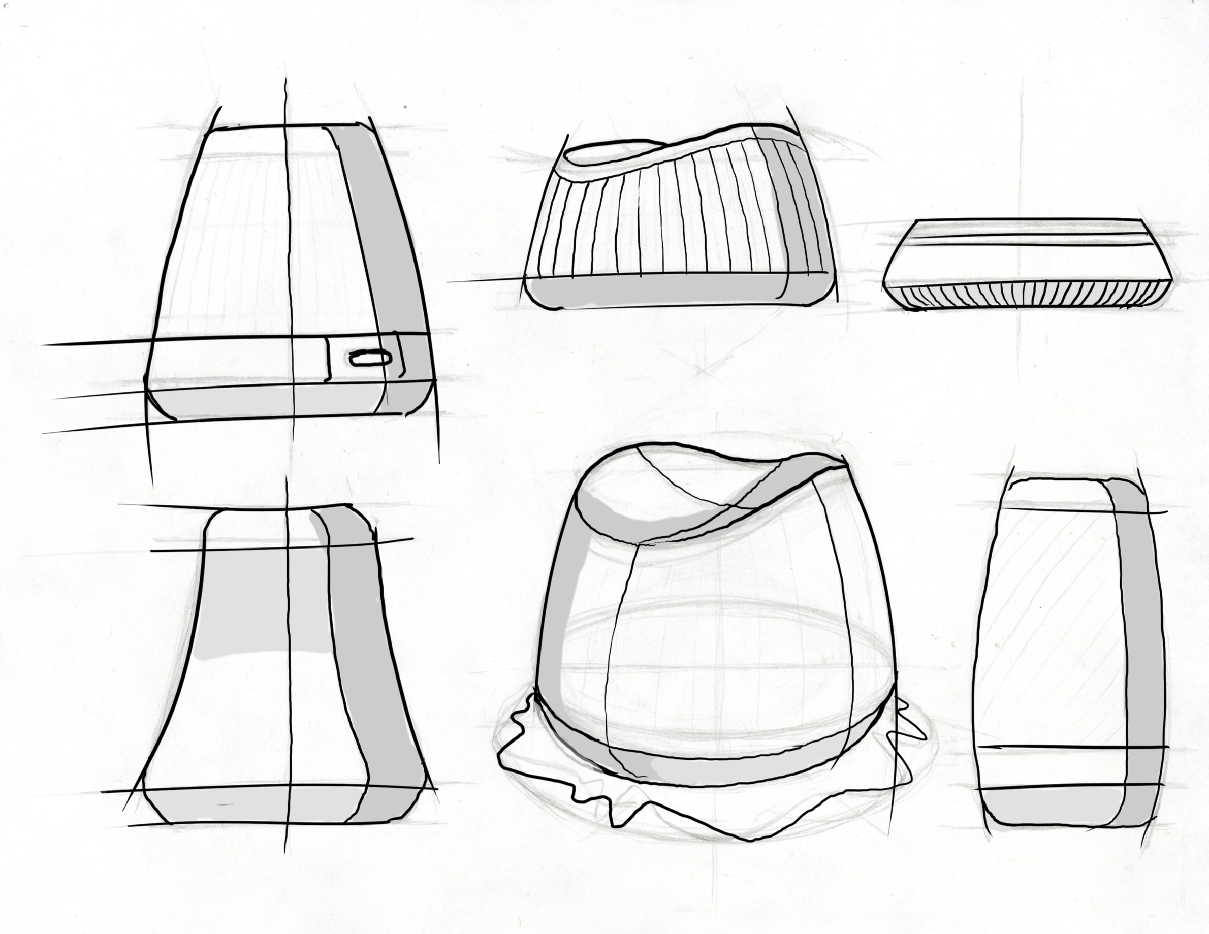
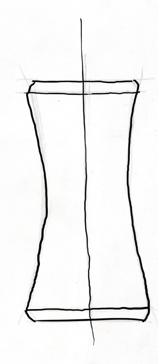
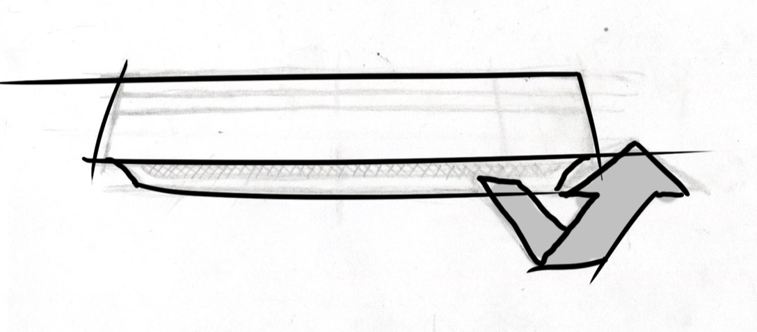
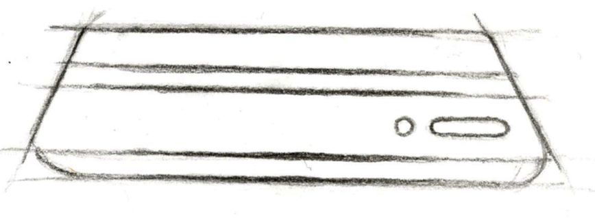
A variety of sketches were made exploring potential exterior forms for my design. The locations and shapes of the LED lights and sensors were experimented with in order to find a configuration that was both visually pleasing and functionally sound.
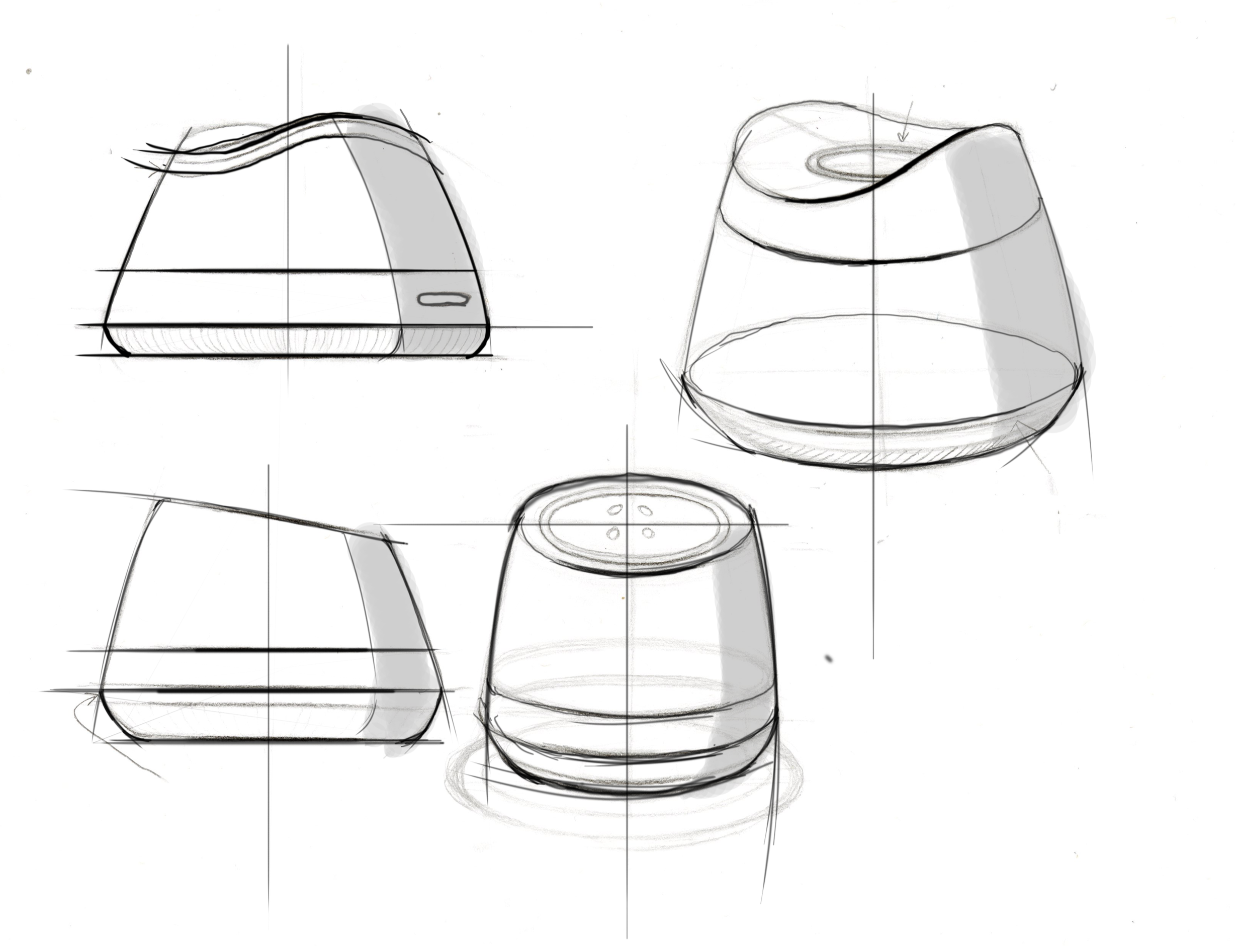
Concept revison
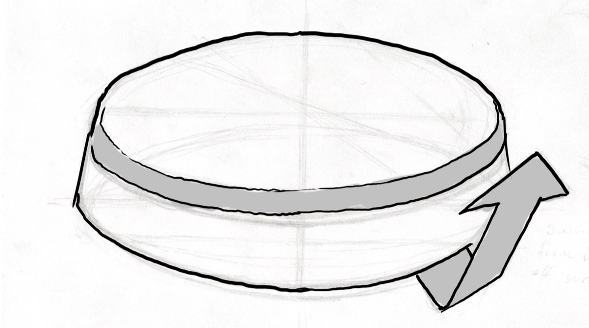
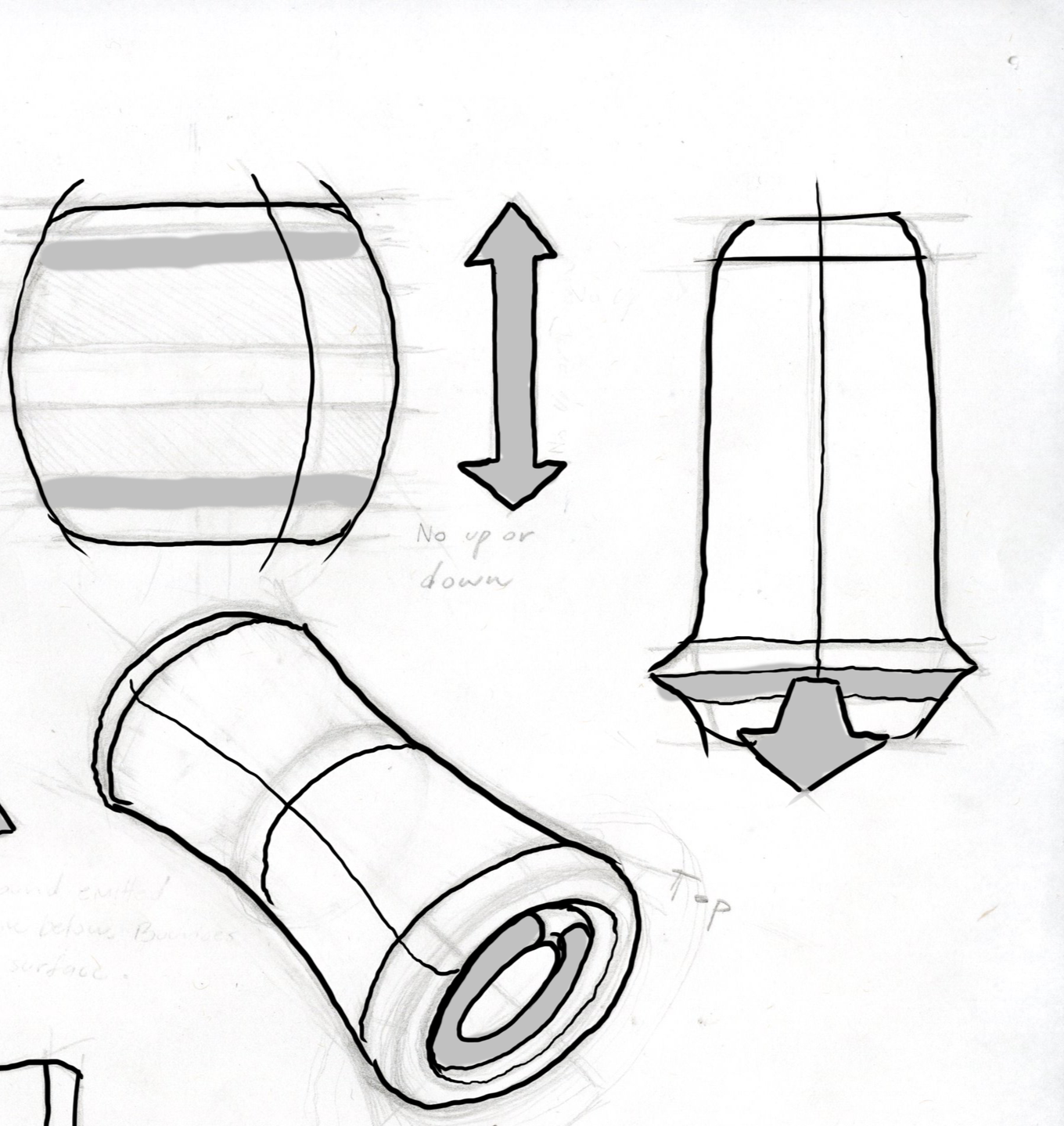
The most successful concepts were further fleshed out and iterated upon in a series of refined sketches. Emerging from this was a silhouette that drew heavily from that of a water droplet, whose unique, bowl-like shape would amplify the light from my LED component.
Final idea


Research
Before production could begin, initial groundwork needed to be done to understand the mechism, how a human would interact with it, and the electronic components that would make it a reality.
HMI flow diagram
It was important to begin thinking about exactly how this product would work and how an individual would interface with it from start to finish. To aid in this, a Human Machine Interface (HMI) flow diagram was made in which every action by the user and every reaction by the machine were plotted.
Advanced flow diagram
From the HMI diagram, several points of interface were identified, and an advanced flowchart was made that described on a more technical level the logic tree that would become the basis for my end product code and circuit.


Research was conducted to search for components and sensors that could be used in a circuit to create the desired user experience that I wanted.
The foundation of the circuit would be an Arduino UNO board, which could be easily programmed.
Accompanying this would be a SparkFun Spectrum Shield, which could convert audio channels into visual light data.
That light data would be interpreted by a simple LED ring light
And the audio data itself would be transferred though a 2.5mm audio jack.

Researching electronic components

Building the circuit
Now that research had been done, it was time to leverage what was learned to create a complete, functional circuit.
Circuit diagram
A circuit was devised based on my research of parts and the functionality outlined in my flow charts. While I had initially intended for the spectrum shield and Arduino UNO to be connected via wires, stacking them on top of one another with header pins proved necessary for a clean circuit.
Circuit assembly
With a collection of parts and a rough blueprint, the process of assembly began. Using solder, the header pins were installed to both boards, ensuring a clean connection between the two components. Much care was given to to the precision of my soldering, as I didn’t want to create any shorts through the narrow rows of pins. When all parts were assembled, a quick test program was run to ensure its functionality.


Coding
With the physical side of design all tied up, all that was left to do was finalize the digital code that would drive the interactivity.
Designing chaos
Early drafts of the LED code resulted in a visual effect of a “speedometer filling up (from green to red) based on how loud or intense the music got. While technically functional, it ultimately lacked the spontaneous energy that music often makes us feel. The code was subsequently rewritten to sporadically glimmer and twinkle in response to beats of music, making it feel more alive and energetic.


Design development
Foam model
Early attempts at bringing this concept into reality provided valuable feedback to further develop the design. While the general shape supported functionality, it became apparent that the overall profile would need to be slimmed down to better evoke a lightweight elegance.


Revised design
A new, thicker design was devised to accommodate the space requirements of the internal components, while still retaining the sleek CMF design queues from the earlier attempt. Notably, the design is overall taller and and the plug ports have been moved further down.


Idealized form
A revised CMF CAD model was made reflecting this new design direction. While undoubtedly more aesthetically pleasing, this compact model ultimately created more problems down the line. When it it was time to create a shell, the narrow silhouette left very little space for the real-world internal components.


Revised design CMF renders


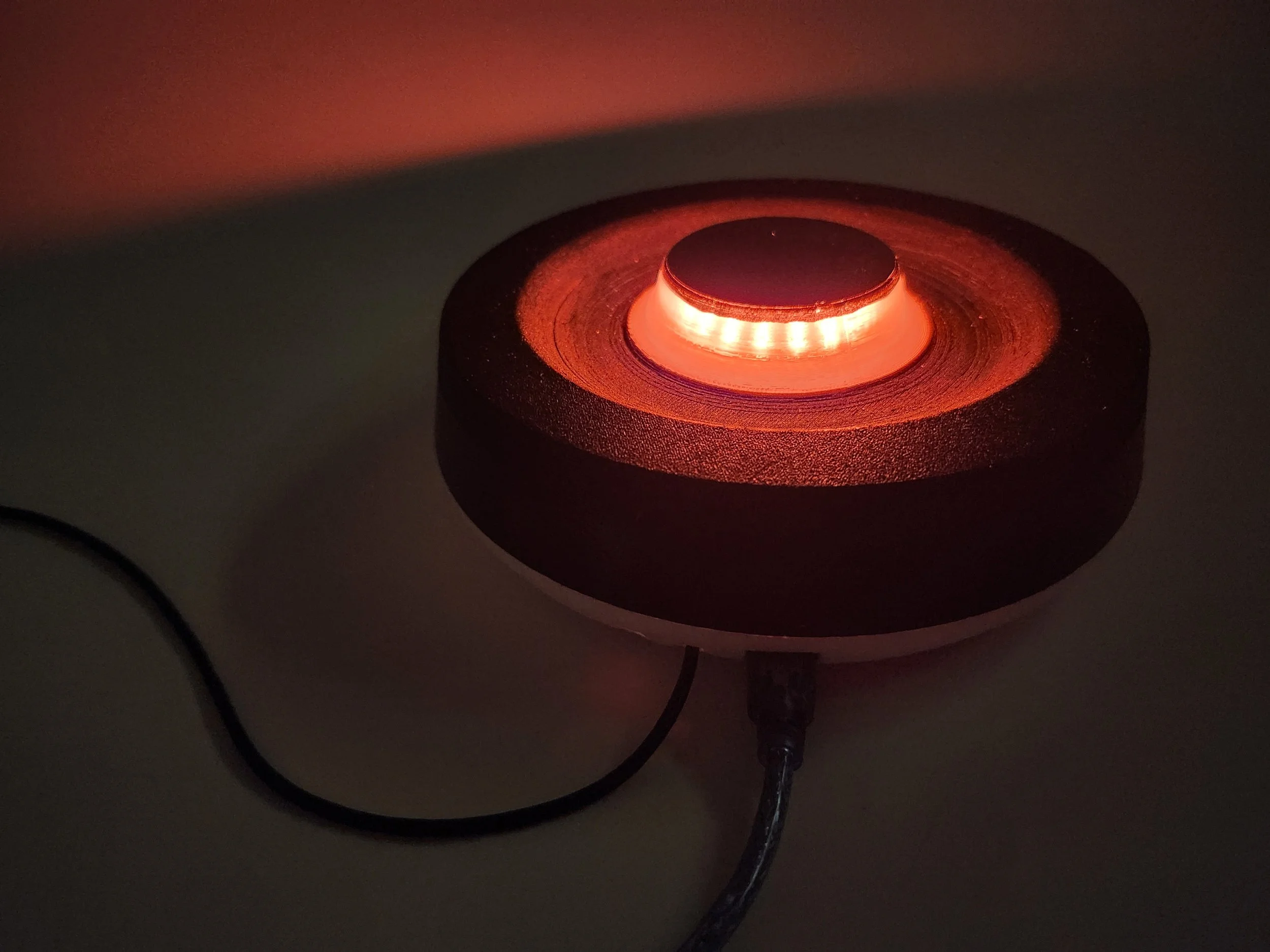
Final prototype
Printing and Construction
With the adjustments made for the internal components, it was then time to construct the final prototype. The shell was printed out on a Bambu printer, cleaned of all its supports, and then tested for a fit with the previously constructed circuit. A diffusion cover for the LED ring was printed from a semi-transparent filament that would better allow light transmission.
CMF
Though this wasn’t a final production model, it was still important to simulate the look and feel that the end users would experience. To achieve this, the model was sanded, masked with tape, and then spray painted with both glossy and matte black finishes. Once dry, the interior was cleaned to ensure no particles from the sanding process would interfere with the electrical parts.


Fully Functional Prototype